贵阳凯佳电力物资

高压配电设备,低压配电设备,真空断路器,真空负荷开关,负荷开关,高压避雷器,电力变压器,万能断路器

联系方式
  • 联系人:李海龙
  • 电话:13595193322
  • 手机:13595193322
  • 传真:13595193322
产品分类
站内搜索
 
友情链接
您当前的位置:首页 » 供应产品 » FN5-12R(L)型户内交流高压负荷开关-熔断器组合电器
FN5-12R(L)型户内交流高压负荷开关-熔断器组合电器
点击图片查看大图
产品/服务: 浏览次数:2999户内交流高压负荷开关  
型 号: FN5-12R(L) 
规 格: 400A 
单 价: 面议  询价
最小起订量:   订购
供货总量:
发货期限: 自买家付款之日起 3 天内发货
有 效 期: 长期有效


«上一个供应产品     下一个供应产品»
详细信息

概述
Summary
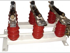
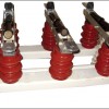
FN5-12R(L)型户内交流高压负荷开关-熔断器组合电器是我厂吸收消化国外先进技术,结合我国的供电要求,自行设计研制而成的。该产品经全面型式实验和长期的试运行考核、性能达到IEC420《交流高压负荷开关-熔断器组合电器》(1990版)和GB3804 《3-63KV交流高压负荷开关》标准要求,与国外同类产品比较,技术参数已达到同类产品水平,具有体积小、重量轻,可用于环网柜和箱式变电站,广泛应用于12KV线路的电能分配,并有效地避免了设备的缺相运行。
该产品的研制成功填补了国内空白,可实现开关、隔离和接地三工位。
It is designed and developed by our own company by bringing in international advanced technology, considering our own country’s specificpower supply. It performances meet IEC420 《AC H.V Load Switch with Fuse》(1990 Edition) and GB3804 《3-63KV AC H.V.Load Switch》after strict test and long-time operating. compared to product of the kind in the foreign country , its technical parameter has reached the international level with the features of small volume and light weight. Can be used in package substation and ring network cebin . It is used widely in 12KV distribution network to protect the equipment againet working without phase.
The sucess of the product fills the domestic gap ,with functions of switch、isolating and earthing.
用途
Use
FN5-12R(L)型户内交流高压负荷开关-熔断器组合电器亦称带脱装置负荷开关(以下简称开关),适用于50Hz,额定电压6-12KV的网络中,可开断负荷电流、过载电流及短路电流,本负荷开关配用CS6-Ⅰ型手动操作机构,本产品专用的CS□手动机构。
It is used in the network of 50Hz rated voltage 6-12KV for breaking load、over-load and short-circuit current , It is equipped with CS6-Ⅰ type handle operating mechanism. It is for the CS□ handle mechanism.
型号含义
Type meaning
额定电流(A)
带脱扣装置(撞针器)
带接地闸刀
带熔断器
额定电压
设计序号
户内负荷开关
Rated current
With tripping gear(striker)
with earth switch
with fuse box
Rated voltage
Designed number
Indoor load switch
使用环境
Serviec Condition
1、海拔不超过1000米;
2、周围空气温度 上限 +40oC 下限-25oC;
3、相对湿度,日平均值不大于95%,月平均值不大于90%(+25oC);
4、周围空气应不受腐蚀性、可燃性气体等明显污染;
5、无经常性的剧列运动;
1、The altitude does not exceed 1000m.
2、The ambient air temperatrue : Max:+40oC. Min:-10oC.
3、The relatire humidity of air Daily average ≤95% . Monthly average ≤90% (temperature:25oC)
4、The ambient air should not be obviously polluted by corrosivity and the flammability gas.Etc.
5、The working situation without frequent violent.
技术参数
Technical parameter
1、负荷开关-熔断组合电器的技术参数见下表:
Technical parameter of Load Swith Fuse box (please see the table)
序号
Number
名称
Name
单位
Unit
参数
Parameter
1
额定电压
Rated voltage
KV 12
2
最高工作电压
Max.working voltage
KV 12
3
额定频率
Rated frequency
Hz 50
4
额定电流
Rated voltage
A 100
5
额定短路开断电流
Rated short-circuit switch-off current
KA 50
6
1min 工频耐受电压(有效值)对地、相间/隔离断口
1min power frequency withstand voltage(value) to ground、interphase/ isolation break
KA 42/48
7
雷电冲击耐受电(压峰)值对地、相间/隔离断口
Lighting impulse resisting voltage (peak) to ground、interphase/isolation break
KV 75/85
8
熔断件撞击输出能量
Fuse link striking output energy
Kg ≈5
2、组合电器所配负荷开关的技术参数见下表。
Technical parameter of load switch with switch with fuse vox (please see the table)
序号
Number
名称
Name
单位
Unit
参数
Parameter
1
额定电压
Rated voltage
KV 12
2
最高工作电压
Max.working voltage
KV 12
3
额定频率
Rated frequency
Hz 50
4
额定电流
Rated voltage
A 630
5
额定负载有功负载开断电流
Rated power load switch-off current
A 630
6
5%额定有功负载开断电流
5%Rated power load switch-off current
A 31.5
7
额定电容开断电流
Rated capacity switch-off current
A 10
8
额定电感开断电流
Rated iductacne switch-off current
A 40
9
额定转移电流
Rated transfer current
KA 1.3
10
额定短时耐受电流
Rated short-time withstand current
KA 20
11
额定峰值耐受电流
Rated peak withstand current
KA 50
12
机械寿命
Mechanical life
2000
外形图
Appearance diagram
1、框架
2、支柱绝缘子
3、支座接线座
4、刀片
5、灭弧管
6、扭簧及扭簧销轴
7、导向片
8、触座接线板
9、拉杆
10、负荷开关转轴
11、弹簧储能机构
12、操作机构
1、Framework
2、Post insulator
3、Bearing wiring board
4、Blade
5、Arc extinguisher
6、Torsional spring and its pin bearing
7、Guide bar
8、Wring board
9、Draw bar
10、Load switch moving bearing
11、Spring energy-storing mechanism
12、Operating mechanism
FN5-12 户内交流高压负荷开关
FN5-12 Indoor AC H.V. Load Switch
 
1、框架
2、接地刀片
3、接地开关轴
4、支柱绝缘子
5、接地转轴
6、支座接地板
7、刀片
8、灭弧管
9、拉簧接钮簧销轴
10、导向片
11、触座接线板
12、拉杆
13、负荷开关轴
14、接线开关弹簧储能机构
15、接地开关弹簧储能机构
16、负荷开关操作机构
17、接地开关操作机构
1.Framework
2.Earth blade
3.Earth switch moving bearing
4.Post insulator
5.Earth moving bearing
6.Bearing wiring board
7.Blade
8.Arc extinguisher
9.Draw spring and torsional spring’s pin bearing
10.Guide bar
11.wiring board
12.Draw bar
13.Load switch moving bearing
14.Load switch spring energy-storing mechanism
15.Earth switch spring energy-storing mechanism
16.Load switch operating mechanism
17.Earth switch operating mechanism
FN5-12D户内交流高压负荷开关
FN5-12D Indoor AC H.V. Load Switch
 
1、FN5-12负荷开关
2、支座熔断器接线板
3、熔管
4、熔断器接线板
5、熔断器支架
注:配RN3熔管电流75A及75A以上的安装尺寸为括号内尺寸。
1、FN15-12 Load switch
2、Bering fuse box wiring board
3、Fuse link
4、Fuse box wiring board
5、Fuse box support
Notes:The installing size in the bracket is for RN13 fuse link with 75A or above 75A.
FN5-12R 户内交流高压负荷开关
FN5-12R Indoor AC H.V. Load Switch
 
1、FN5-12D负荷开关
2、支座熔断器接线板
3、熔管
4、熔断器接线板
5、熔断器支架
注:配RN3熔管电流75A及75A以上的安装尺寸为括号内尺寸。
1、FN15-12D Load switch
2、Bering fuse box wiring board
3、Fuse link
4、Fuse box wiring board
5、Fuse box support
Notes:The installing size in the bracket is for RN13 fuse link with 75A or above 75A.
FN5-12DR户内交流高压负荷开关
FN5-12DR Indoor AC H.V. Load Switch
 
外型图
Apearance diagram
1、FN5-12负荷开关
2、支座熔断器接线板
3、熔管
4、熔断器接线板
5、熔断器支架
注:配RN3熔管电流75A及75A以上的安装尺寸为括号内尺寸。
1、FN15-12 Load switch
2、Bering fuse box wiring board
3、Fuse link
4、Fuse box wiring board
5、Fuse box support
Notes:The installing size in the bracket is for RN13 fuse link with 75A or above 75A.
FN5-12R/S 户内交流高压负荷开关
FN5-12R/S Indoor AC H.V. Load Switch
 
1、低架
2、绝缘子
3、熔管
4、脱扣装置
5、动触头
6、灭弧管
7、导向片
8、静触头
9、分合闸机构
1、Underframe
2、Insulator
3、Fuse link
4、Tripper gear
5、Moving contact
6、Arc extinguisher
7、Guide bar
8、Static contact
9、On-and-off mechanism
 
FN5-12R(L)户内交流高压负荷开关
FN5-12R(L) Indoor AC H.V. Load Switch
 
1、底架
2、绝缘子
3、熔管
4、脱扣装置
5、动触头
6、灭弧管
7、导向片
8、静触头
9、分合闸机构
10、联锁装置
11、负荷开关操动机构
12、接地开关
1.Underframe
2.Insulator
3.Fuse link
4.Tripper gear
5.Moving contact
6.Arc extinguisher
7.Guide bar
8.Static contact
9.On-and-off mechanism
10.Interlock gear
11.Load switch operating mechanism
12.Earth switch
FN5-12RD(L)户内交流高压负荷开关
FN5-12RD(L)Indoor AC H.V. Load Switch
 
安装图
Installation diagram
1、符合开关与CS6-Ⅰ型操动机构联接安装图
Installation diagram for connecting load swith with CS6-Ⅰ operating mechanism
1、插座
2、框架
3、熔断器
4、负荷开关本体
1、Socket
2、Framework
3、Fuse Link
4、Load switch body
 
1、符合开关与CS□操动机构联接安装图
Installation diagram for connecting load swith with CS□ operating mechanism
   
 
1、负荷开关
2、弯连接
3、3/4"焊接钢管(用户自备)
4、操动机构
1、Load switch
2、Connecting bend
3、3/4 welded steel pipe
(provided by users themselves)
4、Operating mechanism
 
操作机构开孔尺寸图
The size diagram of operating mechanism
Cs6操动机构开孔尺寸图
The size diagram of Cs6 operating mechanism
CS□操动机构开孔尺寸图(侧面)
The size diagram of Cs□ operating mechanism (Side)
CS□操动机构开孔尺寸图(正面)
询价单